Arduino Pro Mini
The Arduino Pro Mini is intended for advanced users who require flexibility, low-cost, and small size. It comes with the minimum of components (no on-board USB or pin headers) to keep the cost down. It's a good choice for a board you want to leave embedded in a project. Please note that there are two versions of the board: one that operates at 5V (like most Arduino boards), and one that operates at 3.3V. Be sure to provide the correct power and use components whose operating voltage matches that of the board.
Uploading Sketches
The board comes without built-in USB circuitry, so an off-board USB-to-TTL serial convertor must be used to upload sketches. This can be a FTDI TTL-232R USB - TTL Level Serial Converter Cable for the 5V Arduino Mini Pro), or a FTDI TTL-232R-3V3 USB - TTL Level Serial Converter Cable or the SparkFun FTDI Basic Breakout Board for a 3.3V Arduino Mini Pro. One quick way to connect these is by inserting a six-pin 0.1" male pin header into the end of the FTDI cable or breakout board, and pressing it against the six hole programming header on the Mini Pro. If, however, you're going to be uploading lots of sketches to your Pro Mini, you'll probably want to solder some pins (male headers) to the holes.
If using the FTDI cable on Windows, you'll need to make one configuration change to enable the auto-reset. With the board connected, open the Device Manager (in Control Panels > System > Hardware), and find the USB Serial Port under Ports. Right-click and select properties, then go to Port Settings > Advanced and check Set RTS on Close under Miscellaneous Options.
For the 3.3V versions of the Arduino Pro Mini, select Arduino Pro or Pro Mini (3.3V, 8 MHz) w/ ATmega328 or Arduino Pro or Pro Mini (3.3V, 8 MHz) w/ ATmega168 from the Tools > Board menu (depending on the microcontroller on your board). For the 5V versions of the Arduino Pro Mini, select Arduino Duemilanove or Nano w/ ATmega328 or Arduino Diecimila, Duemilanove, or Nano w/ ATmega168.
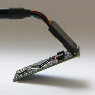
The Arduino Pro Mini connected to (and powered by) an FTDI TTL-232R-3V3 USB - TTL Level Serial Converter Cable. The green and black wires align with the labels "GRN" and "BLK" written next to the holes.
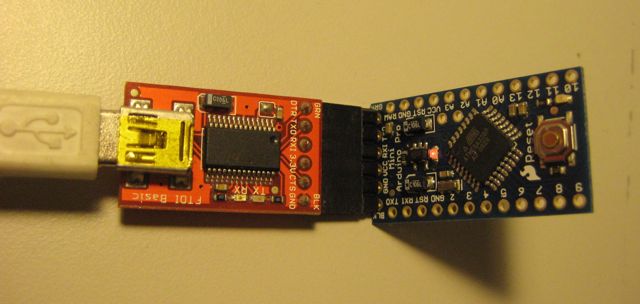
The Arduino Pro Mini connected to (and powered by) a SparkFun FTDI Basic Breakout Board and USB Mini-B cable. Note that on earlier Pro Mini boards the orientation of the 6-pin header may be reversed; check that the words GRN and BLK align on the Pro Mini and FTDI Basic Breakout.
Power
The board can be powered through USB via the six-pin programming header, or from a regulated 5V or 3.3V (depending on the model) supply applied to the VCC pin or an unregulated supply on the RAW pin.
Connectors
Any standard 0.1" spaced header can be soldered to the holes on the Arduino Pro Mini. To use every pin requires two 12-pin headers, plus a six pin header for programming, if desired. Bare wire can also be soldered directly to the holes.
The text of the Arduino getting started guide is licensed under a Creative Commons Attribution-ShareAlike 3.0 License and is based on the Arduino reference. Code samples in the guide are released into the public domain.